PV array
PV isolation and protection


SOLUTIONS / TELECOM
Plan solar charging and DC storage for remote communications, backhaul and monitoring around continuous demand, reserve time, supply polarity and maintenance access.
Application scene illustration
Power architecture
Telecom equipment uses a compatible DC supply path. A separate inverter branch from the battery bus serves the site’s AC auxiliary equipment.
PV isolation and protection
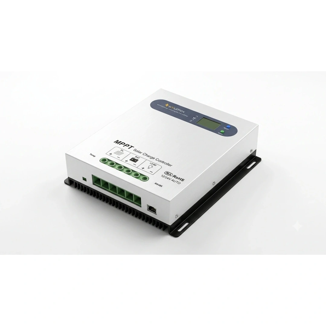
GY4860-MC
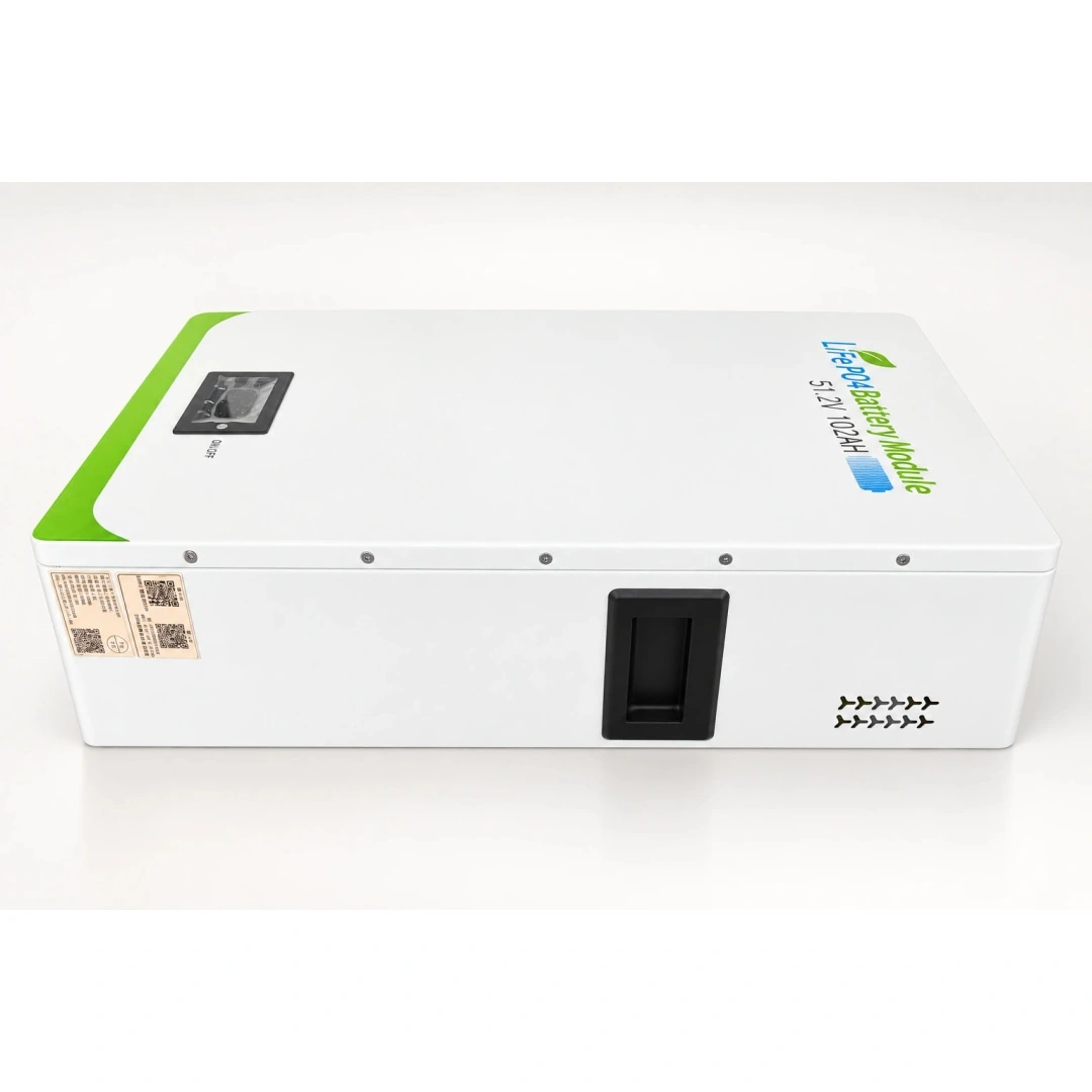
Battery and protected DC bus
Isolated DC-DC where required
Confirm equipment input, such as −48 V
AC auxiliary branch
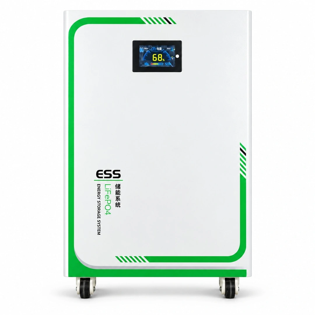
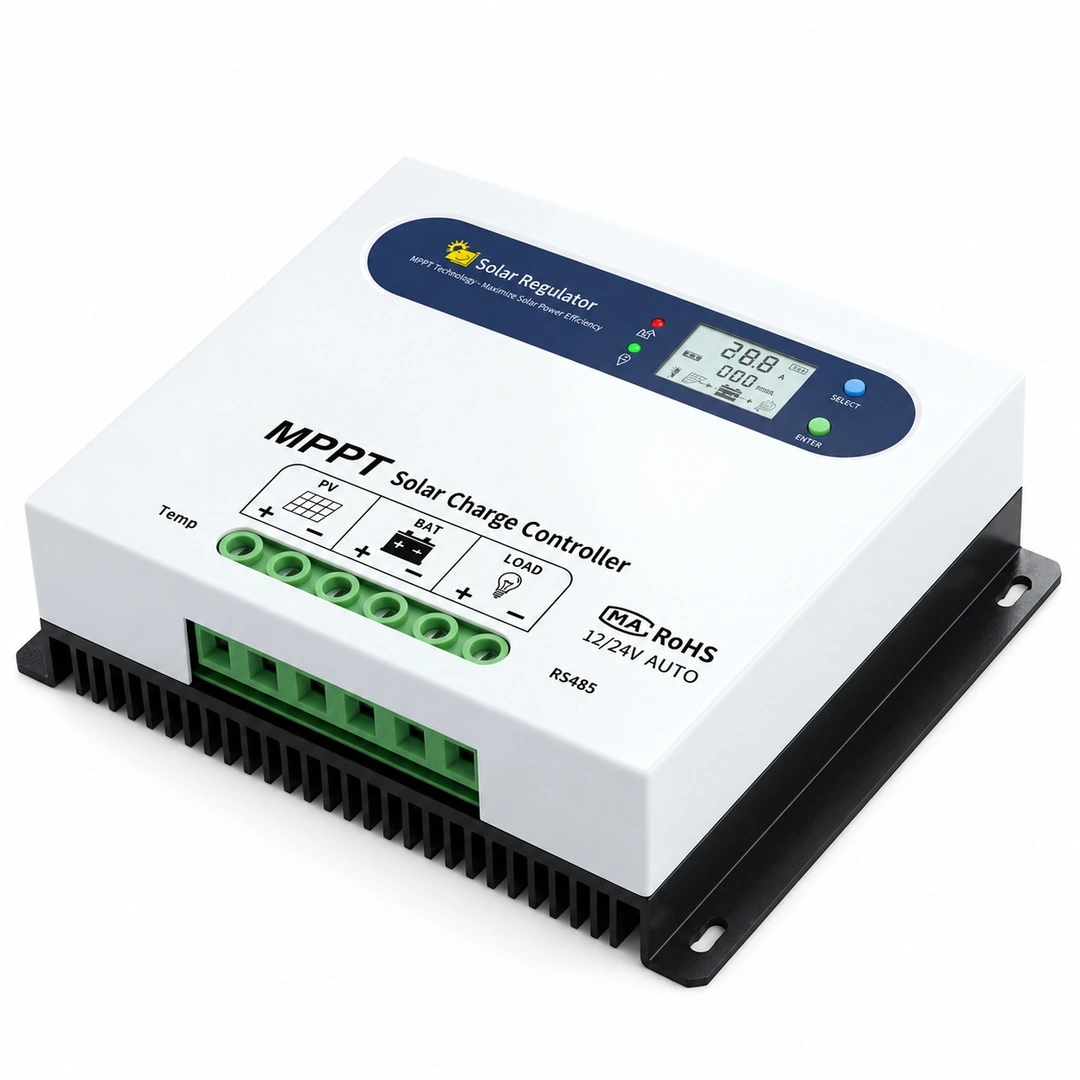
MPPT and battery nodes use existing product images. PV, inverter, telecom supply and loads are companion-equipment illustrations. Final configuration follows site loads and model documents.
| Component | Selection and configuration |
|---|---|
| PV array | Size for daily energy and the site’s low-sun season. Check cold-weather string Voc against the selected MPPT’s voltage, power and current limits. |
| MPPT controller | Choose by battery-system voltage and PV power. The confirmed 40A/60A table supports 12/24/36/48V. Check charging and LOAD-terminal currents separately. |
| LiFePO₄ battery | 48V-class storage is a starting point, subject to the equipment’s complete operating range. Size for continuous demand, reserve time and recharge needs. Nominal 48V is not automatically a compatible −48V telecom supply. |
| Off-grid inverter | Use the inverter for auxiliary loads that need AC, matching the battery’s full input range and auxiliary demand. The main telecom load uses a verified DC power and distribution path. |
| Distribution and site installation | Include PV isolation, battery main protection, DC branches, AC protection, surge/earthing, outdoor enclosures and cable voltage drop in the same design. |
Radio, routing and transmission equipment may operate continuously, with fans or cooling adding auxiliary demand. Record power for the installed configuration and planned expansion, and identify essential services and permissible load reduction.
At unattended sites, reserve duration also depends on maintenance response time. Assess daily demand, low-solar periods and fault-response windows rather than selecting batteries from average load alone.
A “48V system” label does not establish compatibility. Record polarity, grounding, permitted voltage range, isolation needs and the existing power architecture. Equipment marked -48V cannot be matched to a battery by voltage magnitude alone.
GY MPPT controllers use a common-negative design. Where telecom grounding or polarity differs, assess isolation or DC-DC adaptation within the complete system design.
For an illustrative 200W continuous DC load, daily demand is 4.8kWh and two days require 9.6kWh before distribution losses and battery operating limits. This is not a rating for a particular telecom site.
Compare 48V-class 5kWh or 16kWh storage against interface and reserve targets. Check recharge while the site remains operating, including coordinated charging and total current if multiple controllers are used.
Monitor generation, charging current, battery state, load current and faults, with clear remote and on-site responses. GY controllers provide RS485 Modbus; remote integration additionally requires compatible communication equipment and connectivity. An RJ45 connector does not establish Ethernet capability.
Acceptance should cover daytime charge, night supply, low-energy strategy, communication loss and recovery, with settings, circuit identification and maintenance records handed over.
Share interfaces and grounding, continuous/peak loads, reserve time, solar conditions and connectivity. If batteries, PV modules, inverters or chargers already exist, include nameplate photographs and manuals for compatibility review.
These details support a load and energy budget, controller/storage comparison and confirmation of interfaces, installation and protection. Final models, quantities and operating targets depend on the complete configuration review; use the product pages and documentation as the starting point.
UNDERSTAND / YOUR APPLICATION
Plan solar charging and DC storage for remote communications, backhaul and monitoring around continuous demand, reserve time, supply polarity and maintenance access.
Assess continuous loads, backup duration and voltage compatibility for telecom DC supply. Confirm suitability for the specific site equipment.
Architecture overview, not wiring. The controller charges the battery; load supply requires compatible batteries, DC bus, voltage conditioning and protection. Do not assume direct supply from controller load terminals.
ENERGY / VALUE
Select control against PV input and battery needs, not panel wattage alone.
Assess 48 V 5 kWh, 24 V 8 kWh or 48 V 16 kWh against daily demand, usable energy and reserve time; no fixed runtime is promised.
Check battery, PV input, cabling and protection compatibility against the selected model documentation.
APPLICATION / SCENARIOS
Solar and backup storage for telecom sites
PRODUCTS / FOR THIS SOLUTION
SERVICE / PROJECT JOURNEY
Share application, device voltage, peak current, daily consumption and solar panel data for configuration review.
Assess load voltage, peak current, daily energy, PV input and installation environment.
Check battery, PV input, cabling and protection compatibility against the selected model documentation.
Coordinate delivery for the agreed configuration and follow technical service using your enquiry reference.
Tell us what you need. Let’s find the right energy solution together.